Train braking systems, with their unique and complex components, stand in stark contrast to the more familiar air braking systems of road vehicles. The considerable distance trains need to come to a complete stop further underscores their distinctiveness.
Did you know a train can take up to 800 meters to stop when braking at 120 km/h?
According to Joni Martinus, VP of Public Relations at KAI, a train’s braking distance is heavily impacted by factors such as speed, the length and weight of the train cars, and the braking system itself, as reported by KataData on July 24, 2023.
Martinus notes that train braking systems differ significantly from those used in other modes of land transportation, emphasizing that trains require a specific distance for effective braking before they can come to a complete halt.
For many people in Java, trains are a familiar mode of travel. They are a popular means of commuting to work or school and are favored during the annual Eid homecoming season.
With this in mind, the Bawalaksana Central Industrial team is eager to detail the essential components and operating principles of train braking systems.

Fascinating Insights into Train Braking Systems
In Indonesia, the predominant braking system used in trains is the Pneumatic Brake System, which relies on compressed air. This pressurized air mechanism is highly effective for braking because it evenly distributes the braking force across all the train cars. This uniform application is crucial in minimizing the chances of derailment or slipping.
Below, we’ve gathered key information from KeretaListrik.com, which has thoroughly examined the various components involved in train braking systems.
Air Compressor
Like many components in pneumatic systems, the air brake system on trains relies on an air compressor to provide the necessary compressed air. This compressor compresses ambient air and delivers it to a storage tank called the Main Reservoir.
The air pressure needed for a train’s air brake system typically falls within a range of 5 to 10 BAR (72–145 Psi), depending on the specific braking system. Hari Maghfiroh, the administrator of the KeretaListrik website, notes that electric motors and hydrostatic systems usually power the air compressors in Indonesian trains or are directly linked to the train’s engine.
In Indonesia, electric motor-driven compressors are frequently found in KRDI, KRDE, and KRL trains. Hydrostatic compressors are utilized in CC300 locomotives, while engine-coupled compressors are commonly seen in CC20x locomotives, according to Hari, who previously worked with PT INKA Madiun.
Main Reservoir
The next element in the train’s braking system is the Main Reservoir, which acts as a storage tank for the compressed air the compressor generates.
Interestingly, the pressurized air held in this tank serves not only the braking system but also other purposes, such as operating the pneumatic system that controls the opening and closing of train doors.

Driver Brake Valve
The Driver Brake Valve, also known as the train brake lever, is a crucial control mechanism for the train operator. Their skill in managing the braking system’s air pressure is vital, as trains cannot brake suddenly. A certain amount of time is necessary for the air pressure to be evenly distributed across all carriages, ensuring that braking is effective and smooth.
As Joni Martinus, VP of Public Relations at KAI, explains, if the braking pressure is released too abruptly, it can lead to uneven braking. It means the brakes may engage first at the location where the air is released. Joni says, “Uneven braking can cause the train or its carriages to slip, drag, or even overturn,” as KataData reported.
Rail Pressure Gauge
The Rail Pressure Gauge is a specialized device that measures pressure in pneumatic systems aboard trains. In air brake systems, this gauge supplies vital air pressure information to the train operator or crew, enabling them to identify any air leaks or unusual pressure levels.
The Rail Pressure Gauge also allows train crews to monitor the remaining supply of compressed air within the system, which is crucial for ensuring optimal braking performance.
Pneumatic systems on trains also operate automatic doors, making it essential to have an industrial-grade pressure gauge that delivers accurate and reliable air pressure readings. It guarantees that all functionalities work seamlessly and effectively.
Equalising Reservoir
The Equalizing Reservoir is a small pilot reservoir that helps train operators select the correct air pressure for the brake pipe. Understanding its role is crucial, especially for long train formations, as a time delay is essential for the braking system to work effectively.
When the operator pulls the brake lever, the pneumatic braking system doesn’t instantly release air to the brake shoes, halting the train wheels.
Instead, the compressed air is initially directed to the Equalizing Reservoir, as noted by Railway-Technical.com, ensuring that the pressure is evenly distributed throughout the braking system across all carriages.
The Equalizing Reservoir enables the operator to maintain consistent braking performance across the entire train rather than concentrating braking forces solely at the air release point. This component is vital for the safe and efficient operation of the pneumatic braking system.

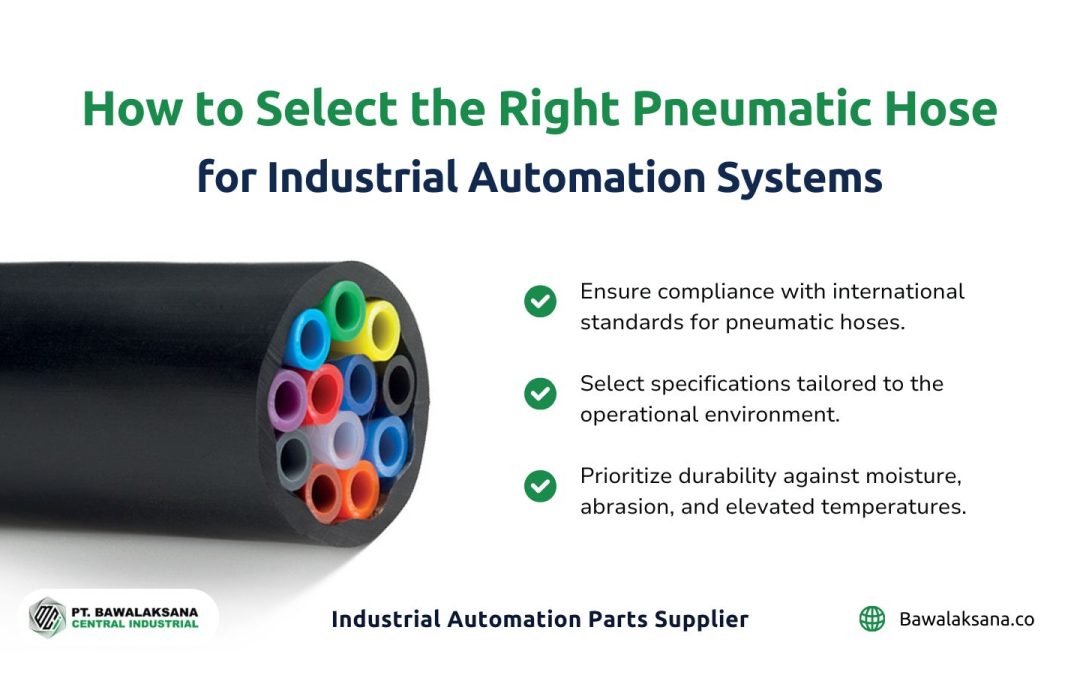
Brake Pipe and Pneumatic Hose
According to TrainTracksHQ, the Brake Pipe and Pneumatic Hose are crucial in distributing compressed air throughout the train braking system. These essential components supply air pressure to the braking system and support other operational devices, such as automatic doors and air suspension systems.
The pneumatic hoses used in air brake systems are crafted from high-quality materials and meet industry standards, including DIN 73378 / 74324 and ISO 7628:2010. This compliance ensures that the pipes and hoses are rigorously tested to function effectively under high-pressure conditions, making them reliable for air braking systems.
Angle Cock
The Angle Cock is an air valve found at the end of each train carriage. This valve opens when the carriages are connected, allowing compressed air to flow from the locomotive to all the attached cars behind it.
The Angle Cock remains in the closed position on the last carriage to ensure that compressed air in the Main Pipe doesn’t escape into the atmosphere.
Brake Cylinder
The Brake Cylinder is a piston that uses compressed air to push the brake shoes against the train wheels. Each carriage has at least one brake cylinder, which connects to a mechanical assembly called the Rigging.
When the Brake Cylinder is activated, it engages the rigging system, causing the brake shoes to firmly contact the train wheels. This intricate mechanical process allows the train’s braking system to function safely and effectively.
It’s worth noting that modern train braking systems often incorporate disc brake components powered by compressed air. The underlying principle is quite similar to that found in many other forms of land transportation.
Auxiliary Reservoir & Triple Valve/Distributor
In a train’s Air Brake System, the Auxiliary Reservoir is a storage tank for compressed air, primarily supplying the Brake Cylinder to initiate braking. The Triple Valve, also known as the Distributor, plays a crucial role in controlling the airflow to the Auxiliary Reservoir for brake applications. It also cuts off the air supply to the Brake Cylinder when the brakes are released.
Dr. Piers Connor, Principal Consultant at PRC Rail Consulting Ltd. and author of Railway Technical, outlines the braking process, which involves several key components of the train’s air brake system. Here are the main points:
- Compressed air stored in the Main Reservoir is distributed through the Main Pipe that runs the length of each train carriage. In each carriage, this pipe connects to the Triple Valve/Distributor, which directs air into the Auxiliary Reservoir and manages storage.
- The Auxiliary Reservoir then supplies compressed air to the Brake Cylinder to enable braking operations, but the Triple Valve/Distributor regulates this process.
- The Triple Valve/Distributor’s function hinges on the variations in air pressure within the Brake Pipe of each carriage, which is linked to the driver’s dashboard (Driver Brake Valve).
- When the air pressure in the Brake Pipe drops, the Auxiliary Reservoir releases compressed air into the Brake Cylinder, resulting in brake application. Conversely, when the pressure in the Brake Pipe rises, the brakes are released, ceasing the braking action.
Below is a diagram illustrating the train’s braking process, as created by Dr. Piers Connor and published on Railway Technical:


We’ve also added a link to an interactive video that explains the various components of the Air Brake System used in trains and details how they function: How does the train braking system work?
The Essential Role of the Rail Pressure Gauge in Train Braking Systems
The Pneumatic Brake System, commonly known as the air brake system in trains, depends on a specialized pressure gauge that serves a vital purpose, as highlighted below:
Monitoring and Regulating Air Pressure
The Rail Pressure Gauge measures the air pressure within the braking system, ensuring that it functions correctly. It provides train operators with a clear visual representation of the pressure levels within the Air Brake System, enabling them to monitor and manage the pressure to remain within safe limits.
Identifying Leaks and Pressure Variations
Maintaining adequate air reserves is crucial for train braking systems to perform optimally. The Rail Pressure Gauge plays a key role in identifying leaks or significant pressure drops. Should the pressure dip below the necessary level, the air compressor will kick in automatically to replenish the Air Brake System with compressed air.
Industry Standards for Air Braking Systems
In the European railway sector, strict standards govern each braking system component, notably DIN 38030:2009-02. This standard pertains explicitly to pressure gauges designed for railway applications, ensuring that these crucial instruments deliver accurate and reliable pressure readings within the train’s air braking system.
This standard is essential, given that trains speeding at speeds of 120 km/h may need up to 800 meters to come to a complete stop.
Consequently, adherence to these industry standards is essential for the safe and effective long-term operation of a train’s braking system.

Moreover, Pneumatic Hoses, which carry compressed air between train carriages, are also subject to stringent quality and durability standards. This regulation ensures that the hoses and tubing are suitable for use in public transportation industries, including railways.
The standards governing Pneumatic Hoses in Air Brake Systems are DIN 73378 / 74324 or ISO 7628:2010. Typically made from Polyamide PHL material, these hoses are engineered to withstand harsh conditions, including exposure to UV rays, oil, and high temperatures.

Recommended Components for Train Braking Systems
Regular inspections and checks are crucial for ensuring the efficient operation of train braking systems. The reliability of this system is crucial for the safety of all passengers and road users.
Trains, particularly those running at high speeds, need considerable stopping distances, making sudden braking impractical. This is mainly due to their long carriages and the heavier loads they transport compared to other forms of land transport.
As mentioned earlier, several key components, such as the rail pressure gauge and pneumatic hose, are vital to the train’s air brake system. We have excellent recommendations for both components, which adhere to the DIN 38030:2009-02 standard for pressure gauges and DIN 73378/74324 for pneumatic hoses.
For the pressure gauge, we recommend the Rail Industry Pressure Gauges from Instruments To Industry (ITI). For the pneumatic hose, we suggest the Rilsan® PA 11 PHL from Mebra Plastik Italia.
For further details about these products, please contact PT. Bawalaksana Central Industrial Sales Engineer team by clicking the contact button below.

Romanta Pinrih Linuwih
Pneumatic Automation Systems Expert
This article was written in collaboration with Romanta Pinrih Linuwih, an expert in Pneumatic Automation Systems, to ensure accuracy and high quality insights.


![10+ Examples of Pneumatic Tools in Daily Life and Industry [2025]](https://bawalaksana.co/wp-content/uploads/2025/05/Sandblasting-large-diameter-pipes-to-remove-surface-contaminants-1080x675.jpg)