Pneumatic cylinders, also referred to as pneumatic actuators, are mechanical devices that harness compressed air to produce linear motion. The underlying principle of pneumatics is rooted in fundamental physical principles first elucidated by the ancient engineer Hero of Alexandria in the 10th century AD.
In contemporary times, pneumatic cylinders find extensive employment within industrial automation systems and cater to diverse applications. These devices are available in various dimensions and motion types, each designed to fulfill specific functions tailored to the requirements of different industries.
In this article, the Bawalaksana team will cover the following topics:
- What is a pneumatic cylinder?
- Types of pneumatic cylinders
- Types of motion that can be generated
- Components found within a cylinder

What is a Pneumatic Cylinder, and What Are Its Functions?
A pneumatic cylinder is a device for converting energy, typically compressed air, into linear motion.
In industrial settings, pneumatic cylinders serve various functions, including moving production items, cutting raw materials, operating conveyors, and facilitating tasks such as packaging, filling, pressing, and product packaging.
In the realm of industrial automation systems, pneumatic cylinders fulfill multifaceted roles across diverse tasks, boasting extensive applications that extend beyond the examples above.
Notably, numerous pneumatic cylinders are engineered to cater to distinct forms and applications within the industrial domain.
Pneumatic cylinders, renowned for their exceptional performance, technological adaptability, and cost-effective maintenance, are highly reliable components within industrial automation systems.
Crucially, these components are integral to pneumatic systems, serving as vital downstream elements and functioning as the “muscle” that propels the pneumatic system.

Types of Pneumatic Cylinders
The landscape of pneumatic cylinders has evolved significantly with the rapid progression of technology, leading to a diverse range of options. Broadly, pneumatic cylinders can be classified into four main types based on their design and motion capabilities:
- Linear Pneumatic Cylinder
- Rotary Pneumatic Cylinder
- Rotolinear Pneumatic Cylinder
- Rodless Pneumatic Cylinder
Linear pneumatic cylinders are capable of generating straight-line motion, either horizontally or vertically.
Rotary pneumatic cylinders are capable of producing rotational motion.
A rotolinear pneumatic cylinder can combine linear and rotational movements.

A lesser-known type, the rodless pneumatic cylinder, operates without a piston rod extending from the body. Instead, it relies on a piston connected to external components, facilitating linear movement through a magnetic or mechanical coupling system.
Rodless pneumatic cylinders offer distinct advantages in applications requiring extended, rapid strokes within limited spaces. They enable the transportation of heavy loads over considerable distances.
While pneumatic cylinders come in various shapes and designs, the linear pneumatic cylinder remains the most widely recognized type.
Moreover, linear pneumatic cylinders can be further classified into two types based on their active movements and the air ports they possess.
In subsequent sections, we will delve into the types of linear pneumatic cylinders and their operational characteristics.

Single Acting Cylinder
A single-acting cylinder is a pneumatic cylinder designed to push or pull a load in one direction actively.
This type of cylinder is equipped with a single air port for pressure. Its primary function is to exert force in a single direction. A spring is incorporated within the cylinder tube to facilitate this action and return the piston to its neutral position.
Single-acting cylinders are further categorized into Push-Type and Pull-Type based on the position of the piston rod when the cylinder is in a neutral (off) state.
The diagram below illustrates the two types of Single Acting Cylinders (Push-Type and Pull-Type):

- Push-Type Cylinder
In a Push-Type Cylinder, the piston rod remains retracted when the cylinder is not supplied with compressed air (neutral position).
Compressed air is required to extend the piston rod. Once the air pressure is reduced or removed, the internal spring pushes the piston rod back to its retracted position.
- Pull-Type Cylinder
A Pull-Type Cylinder behaves oppositely. When there is no air supply, the piston rod is extended (in the neutral position).
Compressed air must be applied to retract the piston rod. When the air pressure is released, the spring returns the piston rod to its extended position.

Double Acting Cylinder
A Double Acting Cylinder is a pneumatic cylinder designed to push or pull loads in both directions through active operation. It features two air ports, allowing air pressure to control movement in both the piston rod’s extension (lengthening) and retraction (shortening).
The key function of a Double Acting Cylinder is to facilitate motion in two directions, making it capable of extending and retracting the piston rod as required. The piston rod’s position can be extended or retracted, and it will remain stationary as long as no compressed air is applied to either port.
In summary, a Double Acting Cylinder adjusts the piston rod’s movement in both directions based on the compressed air supply to the cylinder chamber, ensuring precise control over its extension and retraction.

How Pneumatic Cylinders Work
After understanding the different types of pneumatic cylinders, let’s discuss their general operational principles.
Essentially, the working principle of a pneumatic cylinder is to convert energy (in this case, compressed air) into mechanical motion, which can be either linear (straight) or rotary (circular).
Compressed air enters through the cylinder’s air port, known as the pressure port. The incoming compressed air pushes the piston within the cylinder, causing the piston rod to move in a linear direction.
The stroke occurs when the linear movement of the pneumatic cylinder reaches its maximum limit.
The stroke of the cylinder consists of two states, depending on the actuation of the piston:
- Extension: The piston rod lengthens.
- Retraction: The piston rod shortens.
Next, we will explain how pneumatic cylinders operate based on their types, including single-acting and double-acting cylinders.
How Single-Acting Cylinders Work
A single-acting cylinder is a linear pneumatic cylinder designed to produce straight-line motion in one direction. It operates with a single active actuation direction, either pushing or pulling a load, depending on whether it is a Push-Type or Pull-Type.
The operation of a Single Acting Cylinder involves the following steps:
- Compressed air enters the air port at one end of the cylinder, either the front or rear.
- The pressurized air forces the piston to move, extending the piston rod in a Push-Type or retracting it in a Pull-Type configuration.
- Once the air pressure is reduced or released, the piston returns to its original position, driven by a spring located inside the cylinder.
It’s important to note that the spring within the Single Acting Cylinder plays a crucial role in returning the piston to its neutral or “off” position when the cylinder is not pressurized, ensuring the system is reset for the next operation.
How Double Acting Cylinders Work
A double-acting cylinder is a type of linear pneumatic cylinder designed to produce straight-line motion in both directions. Unlike single-acting cylinders, which operate in one direction, double-acting cylinders have two active actuation directions, enabling them to push or pull a load during extension and retraction.
Key distinctions include the absence of a spring and the presence of two ports for supplying compressed air, allowing the cylinder to control both movements actively.
The operational process of a Double Acting Cylinder is as follows:
- Compressed air entering the port at the rear (Cylinder Cap) pushes the piston and piston rod, causing the rod to extend.
- Compressed air entering the port at the front (Cylinder Head) forces the piston and rod to retract.

Important notes for double-acting cylinders:
- The piston inside the cylinder tube divides the barrel into two chambers with different effective volumes, leading to different force outputs during extension and retraction.
- The effective volume for extension (lengthening) is larger than for retraction (shortening), as the piston rod occupies space in the retraction chamber.
- As a result, the extension stroke generates more force than the retraction stroke, which is typically weaker due to the smaller effective volume.
- This variation in volume also affects the speed and force exerted during each stroke.

How Rotary Pneumatic Cylinders Work
A Rotary Pneumatic Cylinder is a pneumatic cylinder designed to produce rotational motion. Its internal components are more complex than those found in linear pneumatic cylinders. In addition to the piston and piston rod, rotary cylinders incorporate key elements like a rack and pinion mechanism, which converts linear motion into rotational motion.
Rotary Pneumatic Cylinders are available in two main types:
- Single Rack Actuator
- Double Rack Actuator
Depending on the application, each type offers distinct operational advantages, with single-rack actuators typically providing a much greater rotation range than double-rack actuators. We will explain the operation of a rotary pneumatic cylinder as follows:

1. Single Rack Actuator
The Single Rack Actuator features two pistons on the right and left sides that work in opposition, connected by a single cylinder rod equipped with a rack gear. In the center of the rod, a pinion (gear wheel) rotates when the rod moves. This type of cylinder utilizes only one rack gear hence it is referred to as a Single Rack Actuator.
The operation of the Single Rack Actuator is as follows:
- Pressurized air enters the air inlet on the left side of the cylinder, pushing the piston to the right and advancing the piston rod a whole step to the right. This movement causes the pinion in the center to rotate clockwise.
- Conversely, when pressurized air enters the air inlet on the right side of the cylinder, it pushes the piston to the left, moving the piston rod a whole step to the left. This action makes the pinion in the center rotate counterclockwise.
The animated diagram below illustrates how the Single Rack Actuator works:

2. Double Rack Actuator
The Double Rack Actuator features two smaller pistons on the right and left sides that move independently but are synchronized through a central pinion. The pistons are positioned separately (one on the right and one on the left), while the rack gear is located in the center to synchronize the movements of both pistons (refer to the diagram comparing single-rack and double-rack actuators).
As mentioned, this type of cylinder has two rack gears; thus, it is called a Double Rack Actuator.
The operation of the Double Rack Actuator is as follows:
- Pressurized air enters the air inlet on the right side of the cylinder, causing the right-side rack gear to move the central pinion counterclockwise.
- When pressurized air enters the air inlet on the left side of the cylinder, the left-side rack gear drives the central pinion to rotate clockwise.
Notes on Rotary Cylinders
- Rotary cylinders generally cannot produce continuous rotation or rotate more than 180° (this depends on the type).
- In contrast, electric actuators can provide continuous and sustained torque for rotational motion.
- Rotary cylinders can be combined with linear cylinders in production lines that utilize Pneumatic Automation Systems.
- The Double Rack Actuator typically allows for a maximum rotation of 90°.

Components of a Pneumatic Cylinder
Next, we will discuss several components and parts of a pneumatic cylinder. Here are some explanations regarding pneumatic cylinders as quoted from the IQS Directory:
Pneumatic Cylinder Bore
The Pneumatic Cylinder Bore, also known as the cylinder tube, serves as the container for the internal components of the pneumatic cylinder. This cylinder tube has caps on both ends:
- Front Cap (Cylinder Head)
- Rear Cap (Cylinder Cap)
The front cap is located near the piston rod’s extended position, while the rear cap is the piston’s base when the piston rod retracts.
One or both of these caps have ports for the entry and exit of pressurized air, depending on the type of cylinder:
- In a Single Acting Pneumatic Cylinder, the air port is on only one cap (either the Cylinder Head or the Cylinder Cap).
- In a Double Acting Pneumatic Cylinder, the air ports on both the front and rear caps.
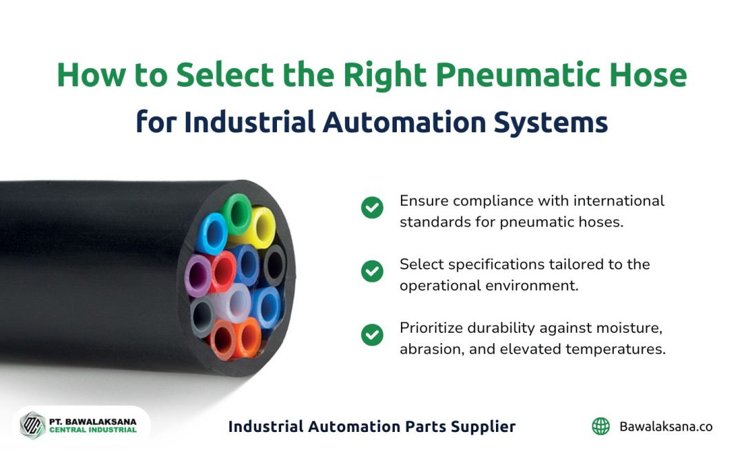
In industrial applications, pneumatic hoses are connected to the ports on the cylinder caps to deliver pressurized air. This air is sourced from an air compressor or an air storage tank. Once the air enters the cylinder, it drives the piston, converting the compressed air into mechanical motion.

Piston
The next critical component is the piston, a disk that is a movable partition within the cylinder tube, dividing it into two chambers. Its primary function is to drive the piston rod, allowing it to extend or retract as pressurized air enters the cylinder.
The piston moves back and forth depending on the direction of the incoming air. When pressurized air enters through the rear port (Cylinder Cap), it pushes the piston forward, causing the piston rod to extend.
This forward motion of the piston rod is called a positive or “plus” movement. The chamber responsible for this movement is the plus chamber, while the opposing chamber is called the minus chamber.
Depending on the pressurized air supply, this alternating motion enables the cylinder to generate mechanical force in both directions.
Piston Rods
As previously explained, the piston rods are directly connected to and driven by the piston. In industrial applications, the end of the piston rod is typically attached to machinery, mechanical components, or objects that require pushing or pulling.
The stroke length refers to the maximum distance the piston and piston rod can travel, which is determined by the cylinder’s overall size and design.
Piston Cushioning
Piston cushioning acts as a damper for the piston and rod during retraction. This feature is essential for reducing impacts, vibrations, and noise during each cylinder stroke. Consequently, the speed of the piston movement can be more stable and faster.

Piston Seal / Gasket
The piston seal plays a crucial role in preventing pressurized air from leaking between the two chambers of the cylinder.
As the piston is a moving partition dividing the cylinder into the plus and minus chambers, the piston seal ensures that air stays confined within its designated chamber, maintaining pressure and preventing cross-contamination between the chambers.
Piston Guide Rings
Piston guide rings are made from chemical-resistant plastics with low friction properties and are designed to protect the piston components. They prevent direct contact between the piston and the cylinder tube, minimizing wear and friction.
These guide rings are commonly made from materials like Polytetrafluoroethylene (PTFE) or polyamide, ensuring durability and smooth operation under demanding conditions.
Sensor
Like electric actuators, many modern pneumatic actuators have sensors to detect the piston stroke position. One such sensor is the Magnetic Proximity Sensor, which leverages the magnetic field generated by the piston to accurately detect its position within the pneumatic cylinder, whether during retraction or extension.
Another commonly used sensor is the Hall Effect Sensor, similar to those found in electric actuators. These sensors provide precise feedback on the piston’s movement, enhancing operational accuracy.

Tie Rods
Tie rods are steel rods that connect the front and rear caps of the cylinder. Typically consisting of four or more rods, they help secure the cylinder assembly and provide protection against external shocks and impacts.
Having outlined several components of the cylinder and their respective functions, we want you to watch the following video, which illustrates how a pneumatic cylinder operates:
Pneumatic Cylinder for Industrial Automation
In this overview, we have examined the fundamental concept of a pneumatic cylinder, the diverse range of available types, and their operational mechanisms. Selecting an appropriate pneumatic cylinder that complies with your application’s specific requirements and industry standards is vital in guaranteeing your pneumatic system’s adherence to best practices.
By gaining insights into the operational principles of various pneumatic cylinder types, you can make an informed decision regarding the most suitable option for your industry-specific needs. A well-informed selection will notably enhance your operations’ efficiency and productivity.

PT. Bawalaksana Central Industrial is the authorized distributor for pneumatic actuators from Metal Work and pneumatic hoses from Mebra Plastic Italy. We extend comprehensive support for your pneumatic automation system, ensuring the effective address of every aspect.
If you need recommendations for the optimal pneumatic cylinder for your application or require top-quality pneumatic components, our proficient team is readily available to offer assistance.
We encourage you to contact us for tailored recommendations and high-quality pneumatic components.
Get in touch with us today to initiate your consultation and ensure that your operations achieve peak efficiency and productivity!

Romanta Pinrih Linuwih
Pneumatic Automation Systems Expert
This article was written in collaboration with Romanta Pinrih Linuwih, an expert in Pneumatic Automation Systems, to ensure accuracy and high quality insights.


![10+ Examples of Pneumatic Tools in Daily Life and Industry [2025]](https://bawalaksana.co/wp-content/uploads/2025/05/Sandblasting-large-diameter-pipes-to-remove-surface-contaminants-1080x675.jpg)